Contents
hide
CNC machining in architecture means using computer numerical control to convert CAD/CAM models into precise architectural parts, and it now includes advanced waterjet cutting alongside routing, milling, turning, laser, plasma, and 5-axis machining.
Since architects began adopting CAD/CAM in the 1990s, CNC has become the digital shop-floor link: machines read G-code toolpaths to move a cutting tool exactly where you tell it, producing consistent results with minimal supervision.
For panel work, typical CNC routers spin ~7,000–18,000 rpm to process wood and composites quickly; for metals, stone, and glass, abrasive waterjet cutting provides clean edges without thermal distortion—ideal for Techniwaterjet-class systems used in architectural fabrication.
You’ll use CNC for scale models, interior fit-out, façades, and construction components such as cladding, stair parts, doors, signage, partitions, lighting housings, and decorative panels.
In architectural terms, it’s the production backbone that translates parametric intent into consistent parts, enabling industrialized off-site workflows.
In this article, you’ll find definitions, current relevance, advantages, details on precision, efficiency, sustainability, and costs, how to choose a partner, applications from models to construction, machine and material overviews, software and BIM/CAM handoff, integration steps, component mapping, limitations, case snapshots, the future (automation + hybrid 3D printing), key file formats, G-code basics, and a short adoption timeline.
Why does CNC machining matter in contemporary architecture?
CNC machining matters because it is the operational link transferring your parametric design into shop-floor reality with accuracy, speed, and consistency. In practical terms, the cnc process reads coordinates and instructions from CAM via G-code, so machine tools know exactly where to move, which cutting tool to run, and when to start or stop.
That digital transfer reduces interpretation errors between computers and the workspace, helping you synchronize architectural design and construction timelines.
It also supports industrialized and off-site construction: consistent router, mill, laser, plasma, and waterjet outputs raise production efficiency and improve on-site fit.
Because architects and engineers now export CAD/BIM files (STEP/STP, STL when needed, and PDF/DXF for shop drawings), the BIM-to-CAM pipeline is cleaner, which helps distributed factories cut identical parts “thousands of miles apart.”
As market pressure for customization grows, cnc technology mass-customized components and repeatable systems that assemble faster on site.
What are the advantages of using CNC machining in architecture?
Precision, speed/efficiency, design freedom, repeatability, and sustainability are the headline advantages you can bank on across architectural projects.
CNC solutions reduce labor costs and stabilize project costs by limiting rework and site improvisation.
There are 5 advantages worth your attention:
- Precision – Tight, material-appropriate tolerances reduce field-fit and improve façade datum alignment, joinery, and concrete formwork interfaces.
- Speed & efficiency – Automated toolpaths, high spindle speeds, and parallel kitting compress timelines and raise throughput for construction projects.
- Design freedom – Complex geometry, intricate patterns, and nonstandard features become manufacturable with consistent quality across batches.
- Repeatability – Identical parts from the same CAM program mean predictable assemblies and fewer surprises during installation.
- Sustainability & waste reduction – Nesting, exact kerf control, and accurate cuts lower scrap; durable fits extend service life and support circular strategies.
How does CNC improve precision for architectural fabrication?
CNC improves precision by maintaining stable, material-appropriate tolerance bands and repeating them across every assembly you produce.
While machine claims can reach extremely fine cuts, architectural accuracy depends on material behavior and fixturing.
Use these practical guides: wood and veneered panels typically maintain tolerances of ±0.25–0.50 mm; plastics such as acrylic or polycarbonate often hold ±0.10–0.25 mm; aluminum and steel plate features typically meet ±0.05–0.20 mm with the right tools and jigs.
Such precision improves panel alignment, consistent gasket compression in façades, and cleaner joins at stairs and casework. Jigged subframes with repeatable drilling patterns keep your datum references aligned, so installers spend less time shimming and adjusting in the field.
For concrete, CNC-cut plywood, MDF, foam, or plastic liners provide smooth pours and accurate curvature, which minimizes grinding and patching. The result is a measurable improvement in accuracy, consistency, and visible surface quality.
How does CNC increase project efficiency?
CNC increases project efficiency by converting automated toolpaths into predictable output that reduces fabrication and installation time. High-speed CNC routers running at 7,000–18,000 rpm cut sheet materials rapidly, while drilling cycles handle fixture holes and hardware patterns in one setup.
Because the same CAM program runs repeatedly, large batches for modular interiors and façades move through machines with minimal touch labor, lowering rework and labor costs.
Off-site prefabrication shortens schedules further: parts arrive kitted, labeled, and packed by module, which cuts on-site exposure to weather and limits coordination overhead. In parallel, you can iterate faster—program changes propagate directly to the cutting path, so prototypes and approvals happen sooner.
That combination—fast machining, batch repeatability, and organized kitting—improves throughput across the construction process and keeps downstream trades on pace.
Techniwaterjet-type abrasive waterjet for mixed materials, you also remove heat-affected delays, preserving edge quality for immediate finishing.
How does CNC expand architectural design possibilities?
CNC expands architectural design possibilities by allowing you to define complex geometry and mass customization without sacrificing quality or schedule.
From freeform surfaces to parametric patterning, machine tools translate your CAD constraints into consistent parts, whether you’re routing wood, milling metals, or cutting composite panels.
You can move from prototype to production with the same digital thread: concept modeling in CAD/BIM, CAM toolpaths, dry runs, then final parts.
Advanced joinery such as dovetails, mortise-and-tenon types, and blind fastener pockets enables clean façades and hidden connectors in interior assemblies.
Latticework, sculptural reliefs, and perforated panels in aluminum, stainless, corian/solid-surface, and HPL composites are straightforward once toolpaths are verified.
Because parametric models feed CAM directly, you can tune spacing, kerf assumptions, and edge conditions to match performance goals for acoustics, daylight, and ventilation.
In short, cnc technology gives you design flexibility at production speed, so customized forms scale across buildings without losing accuracy or finish quality.
How does CNC reduce material waste and environmental impact?
CNC reduces material waste and environmental impact through precise nesting and accurate kerf control to optimize sheet yield and minimize scrap.
Toolpaths follow the geometry exactly, so only required material is cut, reducing rework that wastes resources and time. Offcuts can be cataloged for reuse in small fixtures or future prototypes, improving resource efficiency across projects.
When you specify recycled or low-impact materials—such as recycled aluminum façades or FSC-certified plywood—computer numerical control keeps the visible surfaces clean and the interfaces consistent, protecting thermal and acoustic performance.
Durable, well-fit components extend service life and defer replacements, which lowers lifecycle impacts.
For stone and glass, abrasive waterjet avoids heat-affected zones, preserving edge quality and reducing secondary finishing.
Define “nesting” in your documents, note expected kerf widths by process, and align tolerances with assembly needs; those simple steps translate directly into lower waste, better sustainability metrics, and steadier project costs.
How much does CNC machining cost for architectural projects?
CNC machining costs in US-based architectural projects combine programming, machine time, materials, finishing, quality control, packing, and freight; the final price reflects geometry, quantity, tolerances, and schedule.
Think of the cnc process as a stack: you pay once for setup and repeatedly for cutting cycles, consumables, and downstream work.
Key factors you should plan for include programming/setup, machine time, materials, finishing, QC, consumables/electricity, packing/shipping, and change orders.
Programming and setup typically range from $60 to $150 per hour/
Indicative shop rates:
- CNC router (3-axis) $50–$120/hr
- 3-axis mill $75–$150/hr
- 5-axis $120–$300/hr
- laser $60–$140/hr
- waterjet $90–$180/hr
- plasma $60–$120/hr
Materials:
- MDF/plywood $30–$80/sheet
- solid hardwoods vary
- aluminum $3–$8/lb
- solid-surface $15–$35/sq ft.
Finishing can add $10–$40/sq ft (sanding, sealing, paint; anodize/powder coat varies). Consumables/tool wear average $5–$25 per machine hour; electricity is often in the shop rate, or assume $0.10–$0.25/kWh.
QC, inspection reports, and first-article approvals take time but prevent rework. Crating and freight for oversized panels/modules can be significant—design lifting points early.
Primary multipliers are part size/quantity, material choice, finish spec, tolerance band, and shipping distance; align these with project requirements to control total project costs.
After you’ve mapped out these cost variables, your next focus should be on selecting a cnc machining partner capable of meeting those technical and budgetary expectations with consistent precision.
How should architects choose a CNC machining partner?
Choose a CNC partner who can turn your design and construction intent into reliable parts on schedule and within tolerance.
Start by matching capabilities to your architectural projects: bed size, axes, material envelope, and finishing services must align with the elements you plan to fabricate.
Use the following checklist as your evaluation baseline:
- First, verify available machine tools and processes—routers, mills, waterjet, laser, plasma, and 5-axis plus bed size and fixturing (vacuum, clamps).
- Confirm acceptable CAD/CAM formats (STEP/STP, STL if needed, PDF/DXF for dimensioned drawings) and whether the shop’s posts match its controllers.
- Review portfolio relevance across interior fit-out, façades, and construction components (models, molds/formwork, subframes).
- Ask for documented tolerances by material and their typical cnc milling/router precision; ensure this fits your assembly tolerance stack-ups.
- Assess DfMA support, sample work quality, and surface finish capability. Request prototype runs before full production for stakeholder buy-in.
- Check QC certifications, inspection routines, and reporting. Compare lead times, pricing models, and communication cadence, including BIM/CAM collaboration habits and response time to RFIs.
How is CNC machining applied in architecture?
CNC machining applies across models/prototypes, interior fit-out, exterior/façade elements, and building/construction components, giving you accuracy and speed from concept to install.
The common thread is a digital workflow that turns computer aided design into machine instructions for repeatable parts.
- For models and prototypes, foam, wood, acrylic, and composites communicate form and sequence while allowing rapid iteration.
- Interiors include millwork/casework, wall and ceiling panels, acoustic baffles, screens, stairs, reception desks, and feature lighting components—delivered with kitting and labels for quick site work.
- Exterior systems cover façade panels, rainscreen subframes, louvers, shading devices, planters, benches, and site furnishings; you define datums, hole callouts, and hardware interfaces for clean fit-up.
- Construction components span prefabricated modules, concrete formwork/liners, and structural steel plates with accurate drill patterns for shop assemblies.
In every category, you’ll specify deliverables, tolerance bands, and attachment details so builders can assemble without guesswork and your construction process moves on time.
How are architectural scale models and prototypes produced using CNC?
Architectural models and prototypes are produced by translating your CAD geometry through CAM into CNC toolpaths that cut foam, wood, acrylic, or composites at presentation-level resolution.
The reason this works well is simple: computer numerical control repeats tiny moves exactly, so edges, joints, and textures read correctly at scale.
You begin with concept modeling, export watertight solids or clean 2D contours, generate toolpaths, run a dry check, and then machine.
Resolution is a function of tool diameter, step-over, and material—small cutters and tighter passes yield finer detail on façades, site contours, and interior elements.
Multi-material assemblies combine routed wood bases, milled plastic glazing, and 3D-printed accents, each finished with sanding, sealing, primer, paint, or clear coats.
Because CAM edits propagate quickly, you can test alternatives, collect client feedback, and cut updated parts the same day. The result is a model that communicates intent to engineers, builders, and stakeholders without ambiguity.
Which interior architectural elements are best suited for CNC fabrication?
Interior architectural elements best suited for CNC include casework, wall/ceiling panels, acoustic baffles, screens, stairs, reception desks, and feature lighting components, where consistent geometry and precise holes drive smooth installation.
In practice, cnc router workflows shape panels and drill hardware patterns
in one setup, while cnc milling refines metal or solid-surface details that need tighter tolerances. Where molds and jigs were previously hand-built, CNC-cut molds standardize repetitive details—think curved baffles or repeating stair treads—with repeat accuracy.
You’ll receive labeled kits, installation drawings, and part maps that align with site datums, so crews position parts quickly and reduce labor costs.
Ornate metal accents and precision solid-surface shaping (e.g., Corian) keep visible edges clean.
Use material-appropriate tolerance bands to protect fit at reveals, countertops, and stair guard alignments.
The combination of kitting, labeling, and shop drawings raises production efficiency and turns design flexibility into predictable on-site work.
Which exterior and landscape elements benefit most from CNC?
Exterior and landscape elements that benefit most from CNC are façade panels, rainscreen subframes, louvers, shading devices, planters, benches, and site furnishings—places where alignment, drainage, and thermal breaks matter.
CNC-machined cutouts and slots keep ventilation gaps and joint lines exactly as modeled. For visible metals, laser and waterjet deliver crisp perforation patterns and clean edges without grinding; waterjet avoids heat-affected zones on stainless, aluminum, and even stone or glass.
Subframe drilling patterns repeat across elevations, ensuring datum references stay accurate and minimizing shim stacks.
Coordinate attachment hardware with subframes in your CAD so holes, slots, and stand-offs land where installers expect them. Include drainage paths and thermal break details in shop drawings; precise holes and gasket grooves protect envelope performance.
With consistent parts produced from the same CAM, panels fabricated “thousands of miles apart” match on site, supporting large construction projects with confidence.
Where is CNC machining used in construction-scale applications?
CNC applies to construction scale work wherever off-site manufacturing and accurate interfaces speed assembly. Prefabrication benefits from consistent parts cut in controlled environments, improving throughput and quality.
Concrete formwork depends on CNC-cut plywood, MDF, HDPE, or foam liners to achieve complex curvature and smooth finishes. Structural steel gains from plate cutting, hole drilling, and connection detailing that speed up shop assemblies and minimize field rework.
Hybrid approaches integrate 3D printing for rough forms, with cnc milling passes to hit final dimensions.
Logistics matter at this scale: design modules with transport and lifting in mind, segment large panels intelligently, and mark datums so crews align parts without hunting for references.
Maintain BIM-to-CAM compatibility for multi-trade coordination; shared models reduce misinterpretation and keep the construction industry schedule tight. The outcome is a repeatable method that turns design into site-ready components with fewer surprises.
How is CNC used in prefabricated building systems?
CNC supports prefabricated building systems by panelizing walls/roofs and machining timber components (CLT, GLT) with repeat hole patterns and square, plumb assembly jigs.
The first payoff is predictable geometry: datum strategies define edges, holes, and slots,helping modules align accurately during assembly.
Repeat drilling templates de-risk mechanical and electrical fixture locations, allowing trades to follow a set pattern that fits the model.
In the shop, jigs and clamps hold parts as routers and mills machine openings and pockets in a single pass. On site, labeled kits and documented datums shorten crane time and labor exposure.
Volumetric modules benefit from accurate corner connectors and compound-angle cuts; 5-axis centers handle miters and undercuts in a single setup.
This approach compresses schedules and raises consistency across buildings without sacrificing the design flexibility you expect from modern cnc technology.
How does CNC improve concrete formwork fabrication?
CNC improves concrete formwork by cutting complex geometry liners and reusable panels that yield smooth surfaces and accurate radii with fewer touch-ups.
The main reason is that machines follow your model precisely, so pour lines, reveals, and curvature read cleanly in the finished concrete.
Typical materials include plywood, MDF, HDPE, and foam; each is machined to match the intended surface and paired with appropriate release strategies.
Doubly-curved molds cut on routers or 5-axis centers minimize the need for grinding and patching, and repeat liner sets shorten cycle time on repetitive surfaces.
Accurate hole patterns secure forms to substructures and maintain datum alignment consistent pours. With better fit, you reduce blowouts, honeycombing, and ad-hoc shims, improving both aesthetics and schedule.
Document kerf, tolerance, and fastener patterns in your shop drawings so fabricators and site teams work from the same instructions.
Which architectural features are commonly CNC-fabricated?
Common CNC-fabricated architectural features include bespoke installations, pavilions, feature walls, and parametric façades where consistent accuracy and clean interfaces are critical.
You design ribs, panels, and connectors in your CAD; routers, mills, and waterjet cutters generate parts with consistent edges and holes.
Modules are planned for transport with sizes suited to trucking and rigging, and each module receives labels tied to an installation map.
Hidden fastening strategies—blind pockets, countersinks, and key-slots—create clean visual lines without visible hardware.
For expressive façades, use waterjet or laser for perforations and cnc milling for thicker brackets or frames; for timber ribs, routers shape profiles and drill dowel or cam-lock features in a single setup.
The result is a kit-of-parts that assembles quickly, reads as one continuous surface, and stands up to the realities of site work.
How does CNC contribute to structural steel component fabrication?
CNC contributes to structural steel by raising fit-up accuracy for plates, gussets, and connection details through precise cutting and drilling.
The immediate benefit is bolt-hole alignment: consistent location accuracy and edge quality minimize field reaming and prevent elongated slots that compromise capacity.
Hole tolerances for plate work stay within tight bands when properly fixtured; consistent cope and slot geometry simplifies shop assemblies and allows predictive jigging.
Use waterjet or plasma for plate profiles based on thickness and cost targets; finish-critical edges can be machined after cutting. Shop-assembly mockups validate connection stacks before shipping, catching issues while fixes are fast.
Combined with clear g code and setup sheets, this method improves production efficiency and keeps erection crews on schedule.
How do additive manufacturing and 3D printing integrate with CNC in architecture?
Additive manufacturing integrates with CNC by printing rough forms quickly and then using milling or routing passes to reach final surfaces, holes, and interfaces.
Printed molds or form liners for complex concrete surfaces are common: the printer builds geometry with internal ribbing for stiffness, and a cnc machine finishes critical faces to spec.
Large-format polymer or cementitious prints paired with milling enable fast custom components that still meet tight fit requirements.
Robotic deposition deposition places material along optimized paths; a subsequent machining cycle ensures exact tolerances and attachment points.
This hybrid approach suits prototypes and production, maintaining design flexibility while controlling accuracy.
In short, 3D printing brings speed and shape freedom; CNC delivers precision where assembly and performance demand predictable results.
How does CNC machining intersect with architectural woodworking?
CNC intersects with architectural woodworking by turning routing and milling strategies into consistent joinery, smooth surfaces, and predictable assembly for stairs, baffles, screens, and cabinetry.
Toolpath planning is key: climb vs. conventional passes, step-down choices, and grain orientation affect tear-out and edge clarity.
Routers manage 2D/3D timber work at high speed, while mills tighten tolerances for hardware pockets or metal-wood interfaces.
Digital joinery, including tabs, dogbones, interlocks, and cam/dowel strategies, enables rapid assembly and designs that can be taken apart for maintenance or reuse.
Concealed connectors and blind fastener pockets keep visible faces clean.
Use vacuum fixturing to hold sheet goods and dedicated jigs for repeat parts; post-processing includes sanding, sealing, and finishing compatible with your interior standards.
With good programming and material preparation, you get accuracy, versatility, and cost savings without losing the warmth of wood.
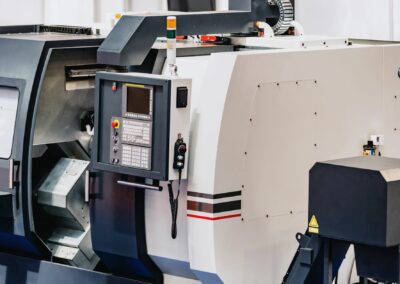
What CNC operations and machine types are used in architecture?
Architectural CNC operations include routing/milling, turning, laser cutting, plasma cutting, waterjet cutting, and 5-axis machining—each matched to materials, cut quality, and tolerance bands.
- Routing and milling cover wood, engineered boards, plastics, and metals
- turning handles round features like posts and standoffs
- lasers excel on thin metals and engineered woods with fine kerf
- plasma targets thicker steel plate
- waterjet tackles metals, stone, glass, and composites without a heat-affected zone
- 5-axis reaches undercuts and compound angles.
Cut quality and heat effects vary: lasers and plasma introduce HAZ on metals while waterjet avoids it but may need secondary machining for tight tolerances.
Routers cut sheet goods and 3D reliefs quickly, while mills produce tighter pockets and precise faces; turning centers offer concentricity on cylindrical parts.
Your process choice balances geometry, edge condition, speed, and budget.
By matching operation to component needs, you protect accuracy, finish, and schedule across construction projects.
CNC routers
A CNC router is a gantry-style machine that moves a high-speed spindle over a table to cut sheet goods and relief forms—ideal for architectural panels, patterns, and casework.
In this context, it’s your workhorse for wood, MDF, plywood, HPL, some plastics, and light metals when required.
Before the list, note that bed size and vacuum fixturing drive throughput: full-sheet capacity and strong hold-down translate to higher production efficiency and cleaner edges.
- Main applications: wall/ceiling panels, casework, acoustic baffles, jig plates, pattern cutting, and 3D surface reliefs.
- Benefits for architecture: fast processing (~7k–18k rpm spindles), integrated drilling of hardware patterns, reliable repeatability for modules, and cost-effective nesting on sheet materials.
- Typical materials: MDF, plywood, HPL, soft/hard woods, acrylic, HDPE, and aluminum composites (with proper tooling).
CNC milling machines
A CNC mill uses rigid linear axes and tool changers to machine blocks and plates with tight tolerances—perfect when architectural parts need precision faces, threads, and pockets.
In architecture, use mills for metal or solid-surface parts requiring higher accuracy than.
Remember: smaller work envelopes often mean tighter tolerances and better surface finishes, ideal for connection hardware and façade brackets.
- Main applications: custom brackets, hardware pockets, precision housings, small façade connectors, and solid-surface details.
- Benefits for architecture: higher accuracy, better surface finish, multi-axis drilling/tapping, and predictable results on metals and solid-surface materials.
CNC lathes and turning centers
A CNC lathe spins the workpiece while tools cut along axes to create rotational features with excellent concentricity. In architectural terms, turning centers deliver repeatable round components.
- Main applications: handrails and posts, baluster details, lighting standoffs, decorative columns, and custom spacers.
- Benefits for architecture: tight roundness, repeatability for large batches, integrated drilling/tapping at ends, and consistent finishes for visible elements.
CNC laser cutters
A CNC laser focuses energy to cut thin metals and engineered woods with a narrow kerf and clean edge—great for perforation patterns and screens. In architectural fabrication, lasers serve when precision outlines and fine features are key.
- Main applications: perforated metal panels, signage, thin plywood elements, and detailed ventilation screens.
- Benefits for architecture: precise cuts, smooth edges requiring minimal deburr, fast throughput on thin stock, and strong repeatability on mass-produced patterns.
CNC plasma cutters
A CNC plasma cutter uses an ionized gas stream to cut thicker steel plate efficiently, suiting structural and bracket fabrication where speed and cost matter.
- Main applications: structural plates, connection tabs, stiffeners, and heavy brackets.
- Benefits for architecture: economical cutting on thicker plate ranges, good productivity for construction timelines, and compatibility with post-machining for tight interfaces.
CNC waterjet cutters
CNC waterjet cutting mixes high-pressure water with abrasive to cut metals, stone, glass, and composites without heat—ideal for visible architectural edges.
- Main applications: stone medallions, metal inlays, complex glass shapes, composite panels, and mixed-material mosaics.
- Benefits for architecture: no heat-affected zone, material versatility, outstanding edge quality for visible faces, and accurate holes/slots that preserve finish integrity.
5-axis CNC machining centers
A 5-axis machining center moves the tool and/or table in five coordinated axes to reach undercuts, compound angles, and complex surfaces in one setup.
- Main applications: freeform panels, deep reliefs, compound-angle brackets, multi-face machining of jigs, and sculptural components.
- Benefits for architecture: fewer setups, better accuracy across complex geometry, cleaner interfaces, and shorter lead times for advanced shapes.
What materials are supported for architectural CNC machining?
Architectural CNC commonly supports wood and engineered boards, metals, plastics, stone, composites, and solid-surface, giving you wide design flexibility across interiors and façades.
Start by aligning material behavior with the CNC technology and finish your project needs demand.
Before the list, remember that nesting, kerf, and tool selection govern performance, cost, and quality.
- Wood/MDF/plywood: economical, fast routing, ideal for panels and casework; consider humidity effects and grain-related tear-out.
- Solid hardwoods: premium interiors and stair parts; plan grain orientation and finishing sequences.
- Aluminum/stainless/brass: strong façade/feature elements; pair with laser/waterjet and follow with milling for precision features; finish via anodizing or powder coat.
- Plastics (acrylic, polycarbonate, HDPE): signage, lenses, screens; manage heat and chip evacuation for clarity.
- Composites (HPL, FRP, ACM): durable cladding and shaped features; both routers and waterjet handle these effectively.
- Stone/glass: waterjet for crisp, non-HAZ edges and intricate shapes.
- Solid-surface (e.g., Corian): thermoformable, machinable for seamless counters and curved panels; mill tight interfaces and bond joints for invisible seams.
What software is used in architectural CNC workflows?
Architectural CNC workflows combine CAD/BIM, parametric tools, CAM, nesting optimizers, and machine controllers/post-processors so your models become reliable toolpaths.
Typical CAD/BIM platforms include Revit, Rhino, and AutoCAD; parametric add-ons such as Grasshopper feed geometry variations straight to CAM. CAM tools (e.g., Fusion 360, Mastercam) translate solids/surfaces into g code while honoring tool limits and feeds/speeds.
Nesting software boosts sheet yield and reduces waste, supporting both budget control and sustainability goals. Controllers execute posts tuned to each machine’s language, ensuring accurate motion.
For data exchange, export STEP/STP for solids, STL when surfaces need triangulated conversions, and PDF/DXF for dimensioned shop drawings and 2D profiles.
Keep version control tight: name parts/layers consistently, track revisions, and align timestamps across teams.
Verify post compatibility early, as mismatched posts can trigger machine-side errors. With this software stack, designers, engineers, and fabricators maintain a clean digital thread from modeling to production.
How should architects integrate CNC into their design and construction workflows?
Integrate CNC by committing early to DfMA, aligning BIM-to-CAM data standards, and planning mockups, tolerances, shop drawings, QA/QC, and site logistics from day one.
Unclear files waste time, while a consistent model and naming scheme lets your fabricator program accurately without guesswork.
Start with file format alignment and version control between architects, engineers, and manufacturers.
Run pilot mockups—partial assemblies or full-scale corners—to validate details and catch conflicts while changes are inexpensive.
Define tolerance stack-ups for façades, joinery, and gaskets; note datum references, hole callouts, and finish directions in PDFs.
Set an RFI schedule and a single point of contact,; respond with marked-up drawings rather than vague notes.
Plan kitting and labeling, packing sequences, crate design, and lifting points so logistics fit the site.
Finally, schedule QA/QC checkpoints: first-article inspections, measurement reports, and sign-offs before ramping to production. This approach keeps your construction projects predictable and your cnc solutions efficient.
Following a well-planned workflow, you can now map CNC capabilities directly onto your next project, moving systematically from concept to on-site installation.
How do you apply CNC capabilities in your next architectural project?
The main steps run from concept through install, linking CAD/BIM, CAM, prototypes, DfMA reviews, production, QC, and site work.
These eight steps outline the complete workflow for architects and builders.
1) Concept and criteria
Define program, performance targets, materials, finish, and tolerance bands. Identify components best suited to CNC and agree on datums.
2) CAD/BIM modeling
Create clean solids and 2D profiles; set layer/part naming, and add hole callouts, kerf assumptions, and gasket grooves as needed.
3) CAM and setup sheets
Translate geometry to toolpaths; select tools, feeds, and speeds; generate setup sheets and run dry checks to protect visible faces.
4) Prototype and stakeholder review
Cut prototypes for client, engineer, and builder feedback. Adjust geometry, joints, and surface treatments quickly.
5) DfMA coordination
Finalize interface dimensions, datum strategies, drilling templates, and kitting plans to support off-site assembly.
6) Production
Run batches with inspection intervals; maintain revision control and capture shop learnings.
7) QC and documentation
Measure critical features; archive reports; approve first articles before scaling output.
8) Packing, shipping, install
Design crates and lifting points; label modules; supply installation drawings, and confirm site access and sequence.
Which architectural components are best suited for CNC machining?
Components best suited for CNC are those where accuracy, repeatability, and clean interfaces control performance and installation time. Map each to the right process, tolerance band, and finish.
- Slatted acoustic ceilings → Router → ±0.25–0.50 mm (wood) → Clear coat/paint; labeled kits for bays.
- Perforated façades → Laser/Waterjet → ±0.05–0.20 mm (metal) → Anodize/powder coat; gasket grooves as modeled.
- Custom stair stringers → Mill/Waterjet + finish mill → ±0.05–0.20 mm → Primer/paint; precise hole patterns for rails/guards.
- Modular cabinetry → Router → ±0.25–0.50 mm → Laminate/edge banding; cam/dowel joinery.
Complex formwork liners → Router/5-axis → Material-specific → Sealers/release agents; repeat sets for cycle time.
This mapping links component intent to cnc machine tools, so your production methods support schedule, quality, and cost targets.
Identifying the right components is just the first step; understanding how those choices impact performance, installation accuracy, and long-term maintenance ensures your CNC decisions deliver real value.
H3 – Why do component choices matter for performance and constructability?
Component choices matter as CNC-ready details ensure assembly accuracy, thermal/acoustic performance, and lifecycle maintenance.
When tolerances match gasket compression, envelope seals hold and acoustic gaps stay within spec.
Repeatable hole patterns and datum control ensure brackets and panels land where they should, keeping installers productive.
Durable finishes minimize touch-ups and replacements, lowering long-term costs. By pairing the right manufacturing methods to each element—router for sheet goods, waterjet or laser for visible metal edges, milling for precision interfaces—you protect aesthetics and performance without sacrificing speed.
What specific component use cases illustrate CNC value?
CNC’s value shows up in clear pairings of material, machine, and tolerance. Perforated metal panels cut by laser/waterjet achieve accurate daylighting patterns with ±0.05–0.20 mm hole location.
Stair stringers in milled steel or aluminum use precise hole patterns to align guards and handrails.
Cabinetry in routed plywood with cam/dowel joinery assembles fast and stays square.
For complex formwork, routed MDF/HDPE liners replicate curvature precisely, improving concrete quality and reducing patching.
These examples demonstrate how matching cnc machining techniques to features, kerf, and finish unlocks design flexibility while keeping site work efficient.
How does CNC machining support sustainable architecture?
CNC supports sustainable architecture by minimizing waste, enabling local fabrication, and producing durable assemblies that extend service life.
Precise nesting sheet yield, while accurate cuts reduce rework that burns materials and time. Mass timber precision supports tight envelope performance with fewer fillers.
Disassembly-friendly joinery and standardized modules allow reuse and support circular economy approaches.
Local or regional shops shorten transport, cutting emissions while keeping production close to site. Material selection matters: recycled aluminum façades, FSC wood, and low-impact composites maintain performance with lower embodied carbon.
Consider energy use tradeoffs by selecting processes carefully (e.g., waterjet vs. laser, router vs. mill) and grouping operations to limit idle power.
Over the lifecycle—materials, fabrication, service, and end-of-life—CNC improves consistency, reduces waste, and supports responsible construction processes without sacrificing design freedom.
What are the main limitations and challenges of CNC machining in architecture?
Despite its benefits, CNC has limitations—cost/CapEx, skills, and scale/transport—that shape how you deploy CNC in buildings. To stay realistic, frame these upfront and plan mitigations with your fabricator.
Four key challenges to considered:
- Capital cost and unit pricing: Machines and setup time can be expensive; outsourcing is common until volume justifies investment.
- Skilled labor: CAM, fixturing, and maintenance require skilled programmers, operators, and technicians; proper training ensures quality.
- Scale and transport: Machine and material envelopes limit single-piece size; divide modules and plan on-site joining.
- Legacy site practices: Traditional workflows may resist digital handoffs; use pilot projects and clear installation drawings to bridge the gap.
Where is architectural CNC headed next?
Architectural CNC is heading toward higher automation, tighter data interoperability, hybrid additive-subtractive workflows, and lower-carbon construction methods that keep projects fast and predictable.
Expect robotic handling to reduce manual touchpoints and improve safety. Additive processes will print near-net shapes, while cnc machine tools finish interfaces to spec.
Integration with BIM, PLM, and digital twins will close the loop from design to operation, improving traceability and performance verification.
Roadmap highlights:
- Automation: palletized workflows, automatic tool changes, in-line inspection, closed-loop adjustments.
- Hybrids: print-then-mill workflows for fast custom parts.
- Data: standardized posts, common data environments, robust revision tracking.
- Carbon: material optimization, local production, and disassembly-ready assemblies.
Together, these production processes allow design flexibility easier to scale across buildings while protecting accuracy, cost, and sustainability.
How will automation and robotics further reduce labor and errors?
Automation reduces labor and errors by standardizing handling, probing, and tool changes allowing cycles to run with minimal intervention.
Palletized work lets machines queue jobs overnight; automated probing checks datums and adjusts offsets in real time.
In-line inspection catches drift before it becomes scrap, feeding corrections back into the controller for closed-loop accuracy.
Robotic loading/unloading keeps operators focused on programming and QC instead of repetitive motion.
The outcome is increased throughput, steadier quality, and safer work with fewer surprises downstream.
How will additive manufacturing advances influence CNC workflows?
Additive advances will influence CNC by enabling larger-format printing in polymers and cementitious mixes, followed by machining passes that establish precision faces and holes.
Printed molds and liners reduce lead time on complex concrete surfaces, while hybrid print-then-mill workflows produce custom parts rapidly and maintain interface tolerances..
As layer heights shrink and deposition controls improve, you’ll machine less and keep only critical surfaces for finishing, balancing speed with accuracy and cost.
How will greater tech collaboration reshape design-to-fabrication?
Enhanced collaboration reshapes workflows by connecting BIM, CAM, PLM, and digital twins inside a common data environment.
Standardized post-processors reduce translation errors; revision tracking keeps shops aligned to the latest model.
Shared models clarify datums, hole callouts, and tolerance bands so builders and manufacturers cut the same part every time.
As performance data flows from operation to design, you’ll refine details that affect thermal and acoustic outcomes, closing the loop across the project lifecycle.
What is the potential for more sustainable CNC construction?
The potential lies in circular strategies, bio-based materials, low-waste manufacturing, and assemblies designed for deconstruction.
CNC precision ensures mass timber accuracy, enabling tight joints and faster dry installations.
Fastener strategies that favor reversible connections allow components to be reused or recycled at end-of-life. Localized production reduces transport emissions, and standardized modules encourage refurbishment rather than replacement.
Together, these approaches bring sustainability goals into daily production while maintaining performance.
Conclusion
CNC machining connects your CAD/BIM models to real parts—from concept models to façade panels, subframes, and construction components—so you gain precision, speed, and predictable quality.
By aligning design flexibility with the right machine tools and materials, you cut rework, reduce waste, and keep construction schedules intact.
The digital thread—CAD/BIM → CAM → CNC—lets you prototype early, validate details, and then scale production with confidence.
As automation, robotics, and hybrid additive-subtractive methods progress, labor requirements decrease, better data interoperability, and cleaner edges on metals, wood, plastics, stone, and composites.
Choose partners who speak your file formats, meet your tolerance needs, and deliver finishing that matches your vision, and you’ll turn ambitious ideas into site-ready components that fit the first time.